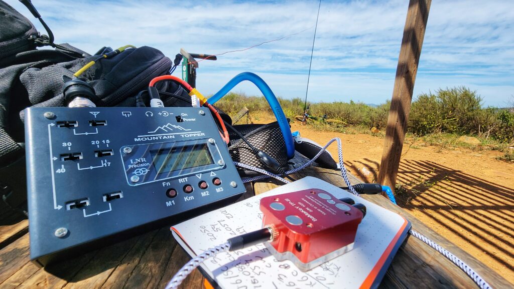
I recently acquired and LNR Precision MTR-5B radio. This is earlier version of the radio that had the four line LCD and the small fonts. It took bit of work to get it up and running but I have been digging it. It is is a fantastic radio
I do have a minor gripe with the sidetone. The radio does not have a main volume adjustment nor sidetone adjustment. I like a lot of folks use an inline volume adjuster with my earbuds. I find that regardless of what the raw volume level I have set with the inline adjustor, the sidetone is too loud in comparison to the bulk of the signals I’m listening too. NOTE: I also own a MTR-3B (Non-LCD) and I have the same minor gripe with the sidetone.
While I have not taken measurements the audio levels, to my ears the sidetone is as loud as a S9 or maybe even a S9+10 signal that this radio would process. The sidetone is at this level all the time. It is not much of a problem when you are getting an S9 signal in as the volume adjuster would be at a manageable level. Where the sidetone is a problem is when I’m trying to work a weak signal and listening really hard with the inline volume adjuster maxed out. When you key down the tone seems extra loud. It could be all in my head but it seems to make the next part of the exchange with that weak signal a bit harder as my ears recover from the loud tone. I have even found myself turning down the inline adjuster while calling CQ and turning it back up afterwards. I wanted to do something about this.
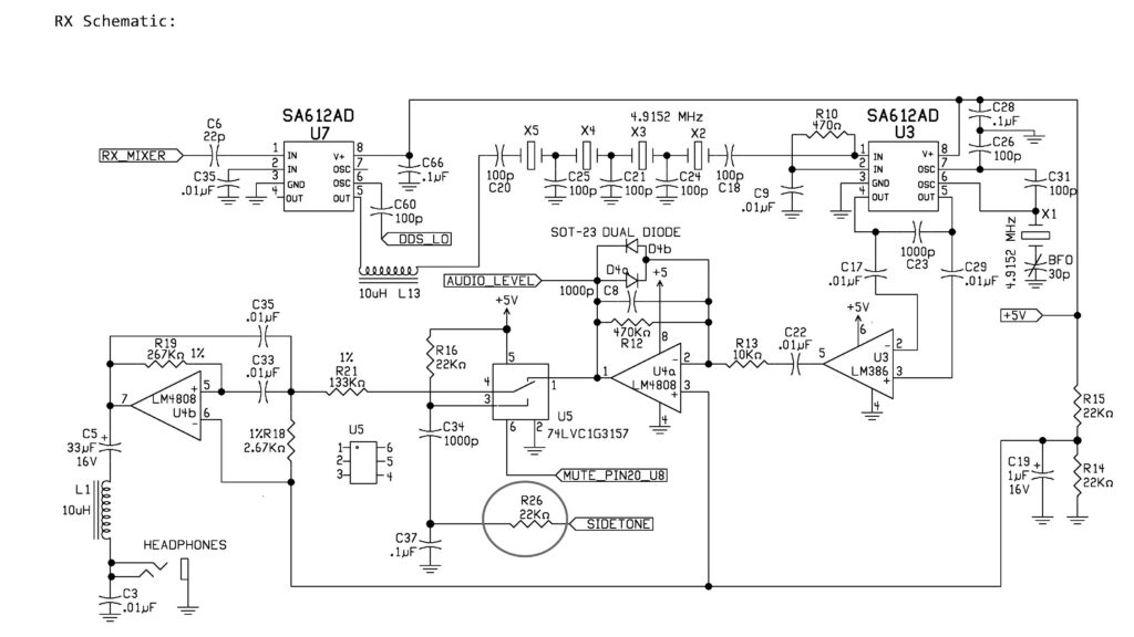
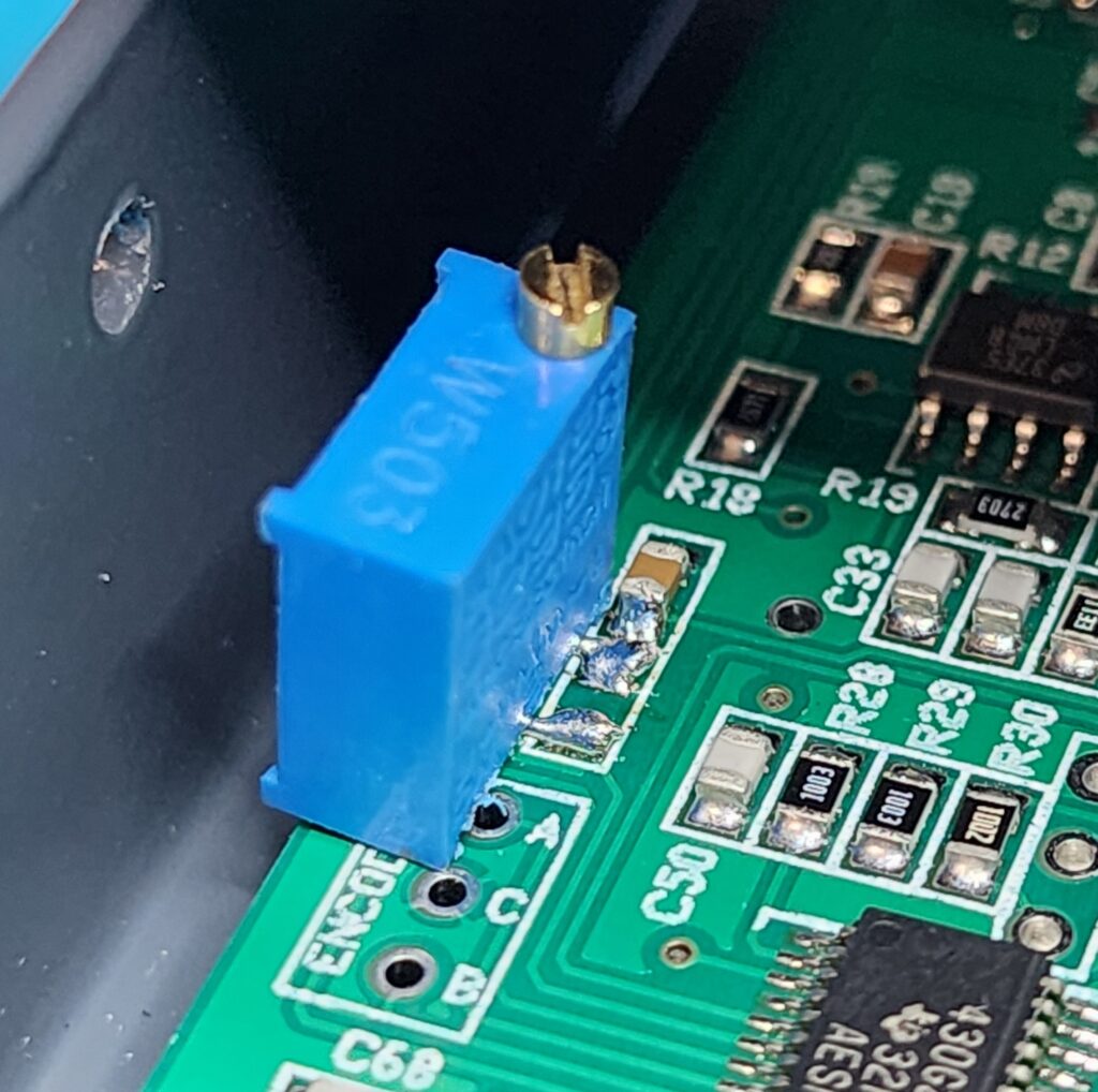
Looking at the schematic, sidetone is generated by the main processor U9 and is routed to U5 Pin3 via R26, C37, C34 and R16. R16 and C34 create a low-pass filter to smooth out the Sidetone signal to make it more pleasant to listen. R26 (an 0805 SMD) is the primary signal injection and attenuation resistor. R26 is where I would focus my efforts. I removed and R26 and temporarily replaced it with a small trimmer potentiometer.
I spent a fair amount of time listening to on the air signals and then switching over to a dummy load and transmitting to evaluate the sidetone level. I would adjust the potentiometer and repeat the listen-transmit cycle until I got the sidetone down to a more balanced level. I would say the sidetone now sounds about like an S5 signal. It is plenty enough loud to be useful, but not so loud that it blows out my ears after straining to copy a week signal. The trimmer measured at 50.5K. I unsoldered the trimmer potentiometer and replaced R26 with 51K 0805 SMD resistor. I am much happier now.
You could do this modification to have a trimmer permanently installed, but would not recommend leaving trimmer leads attached to the R26 pads like I did for testing as pictured above. You are just asking to lift one or both of those pads at some point. If I was going to have a permanent trim pot I would affix the trimmer elsewhere and run some thin insulated wire back to those pads. For me, the permanent lowering of the sidetone level is plenty fine for me.

I have enjoyed this modification enough with my MTR-5B that I have also performed it on my MTR3B (LED). It uses the same circuitry as the MTR5B but the resistor is designated as R20 vice R26. I changed R20 to 51K as well achieving the same results.
UPDATE: I need to step up my Google Foo. After publishing this I went to share my findings on the SOTA reflector and the site let me know there was a similar thread on the topic. Turns out HB9BCB had figured this out in like 2017! Hey new to me radios needing new to me solutions 🙂 It was a good learning experience even if the experience was just new to me. HAM ON!