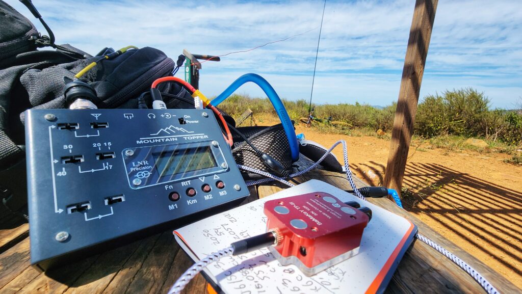
I recently acquired and LNR Precision MTR-5B radio. This is earlier version of the radio that had the four line LCD and the small fonts. It took bit of work to get it up and running but I have been digging it. It is is a fantastic radio
The MTR-5B seeing some MTB SOTA action on Denk Mountain W6/SC-368
I do have a minor gripe with the sidetone. The radio does not have a main volume adjustment nor sidetone adjustment. I like a lot of folks use an inline volume adjuster with my earbuds. I find that regardless of what the raw volume level I have set with the inline adjustor, the sidetone is too loud in comparison to the bulk of the signals I’m listening too. NOTE: I also own a MTR-3B (Non-LCD) and I have the same minor gripe with the sidetone.
While I have not taken measurements the audio levels, to my ears the sidetone is as loud as a S9 or maybe even a S9+10 signal that this radio would process. The sidetone is at this level all the time. It is not much of a problem when you are getting an S9 signal in as the volume adjuster would be at a manageable level. Where the sidetone is a problem is when I’m trying to work a weak signal and listening really hard with the inline volume adjuster maxed out. When you key down the tone seems extra loud. It could be all in my head but it seems to make the next part of the exchange with that weak signal a bit harder as my ears recover from the loud tone. I have even found myself turning down the inline adjuster while calling CQ and turning it back up afterwards. I wanted to do something about this.
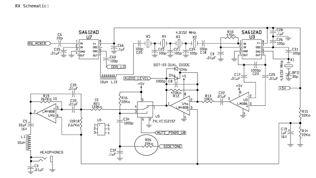
RX Schematic from the MTR-5B (Earlier grey model with 4-line display)
Looking at the schematic, sidetone is generated by the main processor U9 and is routed to U5 Pin3 via R26, C37, C34 and R16. R16 and C34 create a low-pass filter to smooth out the Sidetone signal to make it more pleasant to listen. R26 (an 0805 SMD) is the primary signal injection and attenuation resistor. R26 is where I would focus my efforts. I removed and R26 and temporarily replaced it with a small trimmer potentiometer.
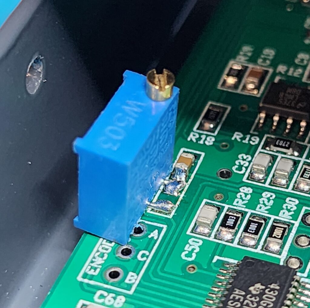
R26 removed and trimmer pot temporarily installed
I spent a fair amount of time listening to on the air signals and then switching over to a dummy load and transmitting to evaluate the sidetone level. I would adjust the potentiometer and repeat the listen-transmit cycle until I got the sidetone down to a more balanced level. I would say the sidetone now sounds about like an S5 signal. It is plenty enough loud to be useful, but not so loud that it blows out my ears after straining to copy a week signal. The trimmer measured at 50.5K. I unsoldered the trimmer potentiometer and replaced R26 with 51K 0805 SMD resistor. I am much happier now.
You could do this modification to have a trimmer permanently installed, but would not recommend leaving trimmer leads attached to the R26 pads like I did for testing as pictured above. You are just asking to lift one or both of those pads at some point. If I was going to have a permanent trim pot I would affix the trimmer elsewhere and run some thin insulated wire back to those pads. For me, the permanent lowering of the sidetone level is plenty fine for me.
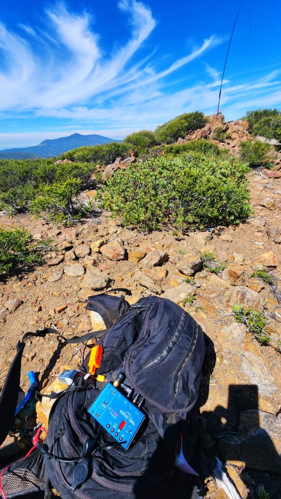
The MTR-3B(LED) also known as “My Little Blue Buddy” in its natural environment
I have enjoyed this modification enough with my MTR-5B that I have also performed it on my MTR3B (LED). It uses the same circuitry as the MTR5B but the resistor is designated as R20 vice R26. I changed R20 to 51K as well achieving the same results.
UPDATE: I need to step up my Google Foo. After publishing this I went to share my findings on the SOTA reflector and the site let me know there was a similar thread on the topic. Turns out HB9BCB had figured this out in like 2017! Hey new to me radios needing new to me solutions 🙂 It was a good learning experience even if the experience was just new to me. HAM ON!
I have both a KX2 and a KX3 and they are both fantastic radios. I have the internal battery and charger options offered for both of those radios. The 3S LiPo battery and internal charger combination used in the KX2 to be great. I find the NiMH batteries of the KX3 with the output power limit of 5W coupled with the “manual” internal charging to not be ideal. I have already done a mod to allow the use of LiFEPO4 14500 battery cells but the issue of removing the batteries to charge them is still a pain. (Link to that mod) I have also looked into an internal LiPo battery mod where you use the same battery used with the KX2 but that modification had a cable hanging out of the radio for external charging. That same cable was then plugged into the radio’s 9-15V DC jack to power the radio. (Link to this mod).
Implementing those modifications helped solidify what I desired for my KX3. That is an internal LiPo battery that is charged internally from the EXT DC jack just like the KX2.
Design: I would rather not have an unproven design that could cause RFI or riskily charge the battery while inside of the KX3. The KX2 internal battery charger (p/n KX2IBC) paired with the KX2 internal battery (p/n KXBT2) is a proven safe design that is RF quite. I went down the rabbit hole of creating PCB that “repackages” the KX2 internal charger circuit into a form-fit that will fit in the KX3.
I did not spend too much time investigating implementing the RTC functions in my PCB. Once I realized the KXBC3 board uses a custom programmed PIC chip, I moved onto focusing on repackaging the charging circuit. Additionally, since the same PIC creates the battery monitoring data for the KX3, I opted to not try and replicate the battery monitoring signals in my design. The battery voltage will be reported as the power supply voltage.
Space: The AA battery holders as well as the KXBC3 PCB need to be removed to make room for the 3S LiPo battery. The KXBC3 provides the NiMH charging circuits as well as the Real-Time Clock functionality. The NiMH charging will clearly not be needed after my modification, but what about the RTC functions. I did not spend too much time investigating implementing the RTC functions in my PCB. Once I realized the KXBC3 board uses a custom programmed PIC chip, moved onto focusing on repackaging the charging circuit. I would use Steve Gollub’s (DL9TX) 3D print designs as starting point for my effort.
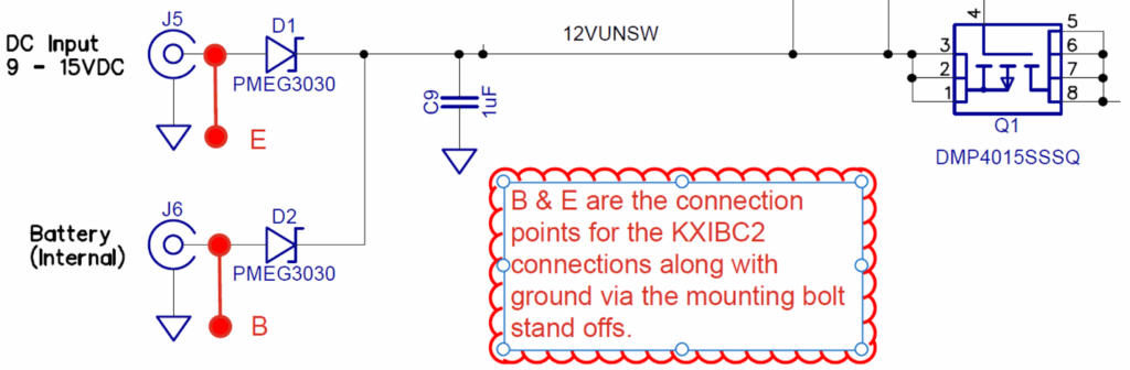
Merging the KX2 design into the KX3.First let’s look at the KX2 design, The charging functionality of the KXIBC2 board basically has three connections: Ground, external power and the battery connection. D1 and D2 provide the “OR” function that has the radio drawing power from whichever source as the higher voltage.
Figure 1 – Part of KX2 Schematic
Figure 2 – Part of the KX3 Schematic
The E and B connections for the KXIBC2 design can be easily replicated in the KX3. The KX3 does not have the “OR” functionality between the external and battery sources. That can be replicated on the PCB design.
Figure 3 – My Starting KX3 LiPo Mod Design
Fast forwarding through the whole KiCad PCB design and prepping, I got the board sent for fabrication and before long I had some prototype boards in from the PCB manufacturing house. Time for some testing.
Figure 4 – My PCB DesignMy Test Setup
Testing and Modifications of the Design
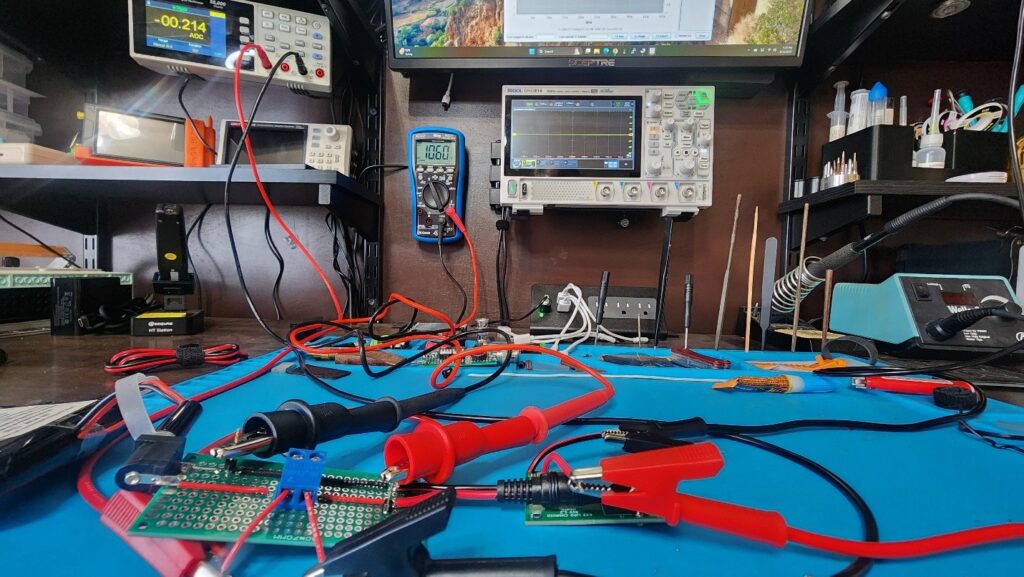
Figure 5 – My Test Setup
I made a solder up bread board that that would be in line with the charger PCB and the battery. From here I could monitor both the current and voltage to the battery. The two multimeters were also connected to my bench computer so the data could be logged off. During the first tests I discovered I have selected the incorrect diodes to be installed by the PCB house. Diodes D3.1 and D3.2 were supposed to be BAV70-5 but I picked BAV70-6. The big difference there is the diodes are reversed internally…Dooh!<Yeah, that is why we test> While waiting for the updated parts, I decided that the 220-250ma charge rate was extremely conservative for a 2600mah battery. R1 in conjunction with Q1 and Q6 sets the maximum charge current. Here is the description from the KX2 manual.
Q1 and Q6 is a current limiting circuit. Current is largely set by the voltage drop across R1 equaling the drop across the base-emitter junction of Q6. As current increases past this point, Q6 collector current also increases, shunting Q1 base current through Q6, and reducing the current through Q1. Actual current will be somewhat dependent on the voltage differential across Q1, being slightly higher when charging starts, and decreasing as charging nears completion.
Using one of my other boards as a donor, I put another 3.3 ohm resister in parallel with R1 to create at 1.65-ohm resistor network. This lower resistance will require twice as much current to produce the emitter-base saturation voltage of Q6 (0.95V) which sets the limit current.
With the proper diodes installed the next round of testing showed an initial charge current around 480ma that quickly settled into 410ma. This equates to charge rate of about C/6 or C/7. The charging stopped at the advertised/expected at cutoff voltage of 12.43VDC. Within seconds this settled down to the open circuit voltage of 12.25VDC
Figure 6 – R1 changed to 1.65 Ohm
At this point, I was extremely happy with the charging rate, but I wanted to optimize the charge cutoff voltage to get the final charge a little closer to 100%. The voltage divider network of R2 and R6 provide the scaled representation of the battery voltage to the comparator U1. Increasing the value of R2 or decreasing the value of R6 would lower the voltage at their junction which U1 uses to determine when to shutoff the charge circuit. The current value of R2 was 133K. A value of 134.6K should raise the charge rate to 98%. 134K SMD resistors are hard to come by, so I sourced a 135K resistor.
Testing with the new R2 value of 135K resulted in charging cutting off at 12.53V. This surface charge voltage equates to about 97% charge. As expected, the open circuit voltage settled in at 12.41V. I was very happy with those results.
Figure 7 – R2 increased to 135K ohm
The final modification was to swap out the two parallel 3.3-ohm resistor network that make up R1 to a single 1.6-ohm resistor. The 1210 resisters are rated at 500mW. This is no where close to an issue with the two 3.3 ohm resistor in parallel but the single 1.6 ohm resistor is closer to its max rating. Even if the charge current was 500ma the power would within the resistor’s rating (.500A * 0.95V = 475mW).
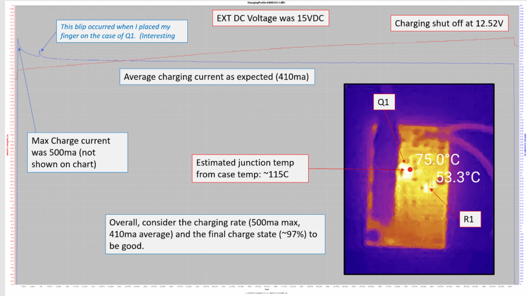
The next rounds of testing added the use of thermal camera to monitor the PCB. The results of those tests showed R1 to be well within thermal limits and below it derating threshold value. Q1 was interestingly hot with a maximum case temperature of 77C and an average case temperature 75C over the charge cycle when the external charge voltage was at the maximum of 15VDC. The die junction temperature is estimated to about 115-125C. The datasheet lists a maximum die temperature rating of 150C so it closer than I would prefer but is acceptable. When charged at the typical vehicle and ham shack voltage of 13.8VDC, Q1 averaged over 15C cooler over the entire charge cycle. (If I do further revision to this PCB, I’ll look to improve the heatsinking of this component)
My intended charging method is use my 13.8VDC from my base station power supply when at home and to use a 15VDC USB-PD cable and a power bank when away from home.
Figure 8 – Final Design Test at Maximum external DC VoltageFigure 9 – Final Design Test at 13.8VDC for external voltageFigure 10 – Final Design
Installation
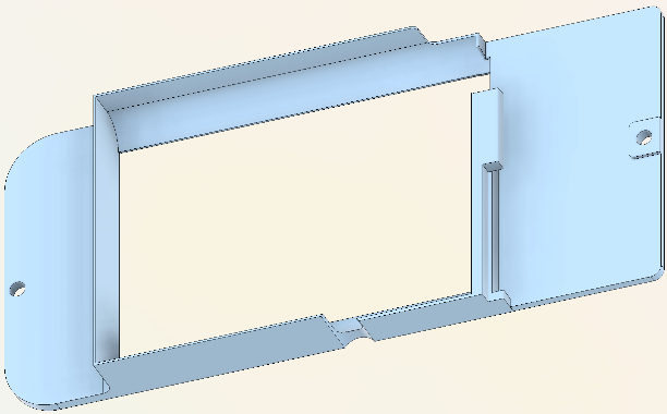
I modified the Stefan Gollub Li-Ion battery holder design quite a bit. The retainer board, that replaces the stock KX3 charger board/NIMH battery retainer, was modified to also replace one of the PCB standoffs by incorporating into the retainer. This increased the space for the battery by 1.5mm. His battery holder design was heavily modified to also house the charger PCB. It was also optimized for better vertical clearance for the battery.
Figure 11-A Battery and PCB holderFigure 11-B Battery RetainerFigure 12 – Completed Mod
Figure 12 – Completed Mod
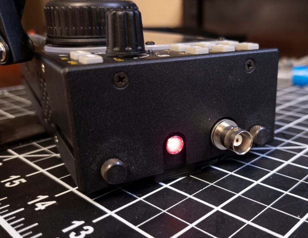
The charge LED on the PCB can be seen through the opening in the case for the external DC jack with most DC barrel plugs, but you have to look at just the right angle. I do not have a 2M transverter module in my KX3 so I was able to reutilized that antenna jack opening to mount and LED to provide charge indication.
Figure 13 – External Charging LED
Overall, I’m quite happy with how this project turned out. I have taken the KX3 out on couple of activations already and it is nice to have 10 watts at the ready. Also super nice to just plug it in and let in charge when you get home. Many thanks to Stefan Gollub’s (DL9TX) for his 3D model designs which spurred on my ideas with this project.
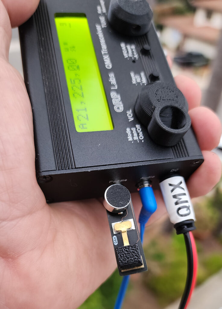
Do you think cables suck? Do you think both the N6ARA Tiny Paddle and the K6ARK mini mic just are just too bulky or lacking in functionality? Well then this hack is for you! Joking aside I love both of these amazing creations by Ara and Adam. I like to have separate kits for each of my radios and you can bet that if the radio can do sideband Adam’s mini mic is going to be in that kit. If the rig does CW you can bet that Ara’s tiny paddle is stashed in the kit as either the backup key or the primary key.
Since SSB has been added to the QMX, I have been thinking about doing the 1lb POTA challenge. The 1lb POTA challenge is activating a park (10 contacts) with at least 1 digital, 1 voice and 1 CW QSO as part of those 10. The radio, antenna, battery, mic, key and cabling all have to come in under a pound.
The Tiny Paddle Mic Hack
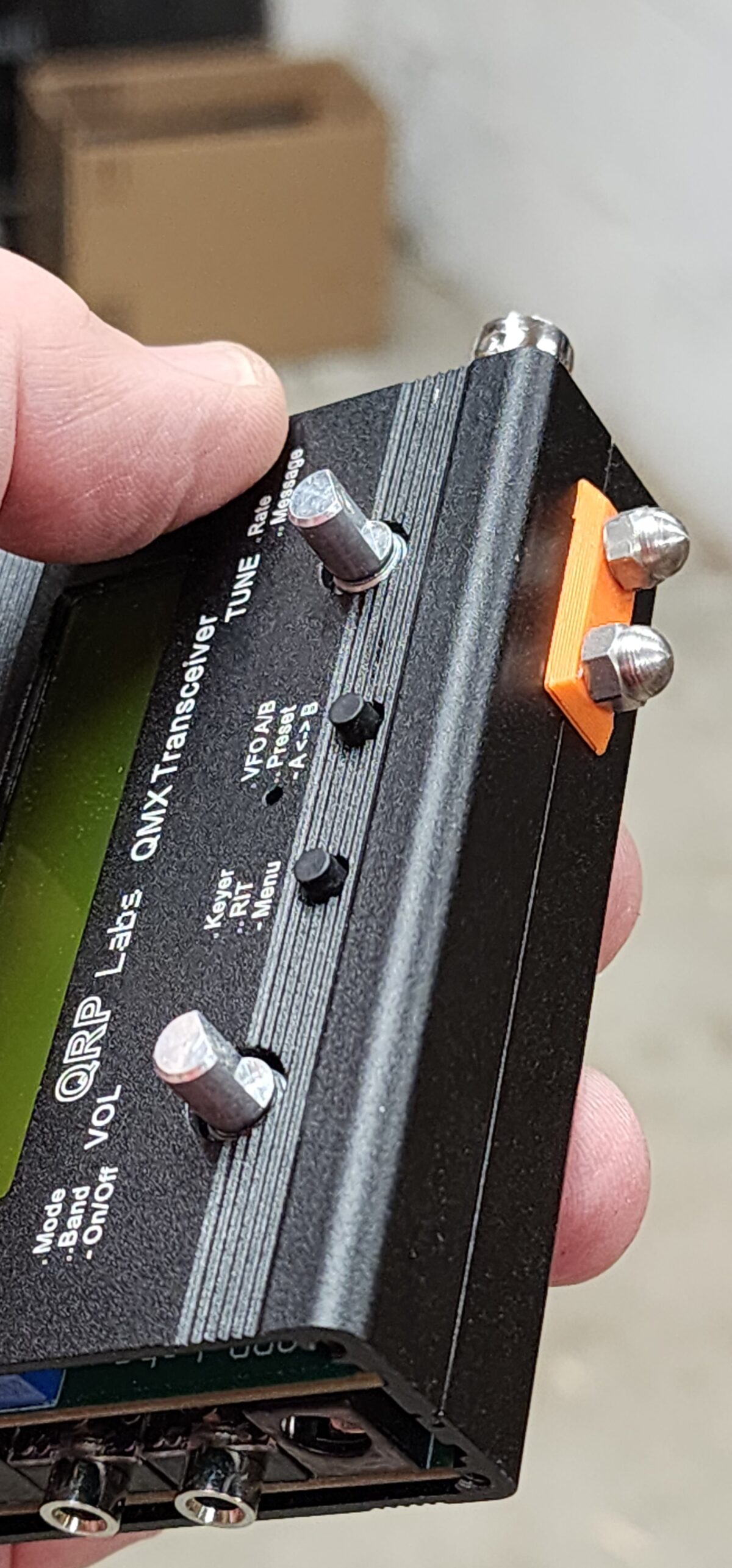
With the QMX using the paddle jack as the mic jack when in SSB mode, I had an idea. That idea lead to me doing a thing!
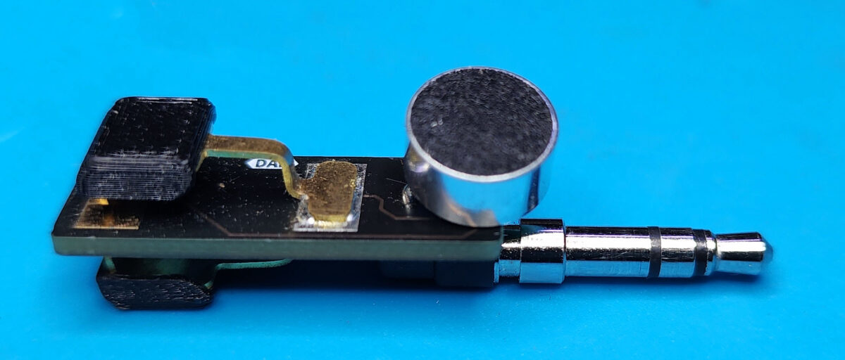
The recommended microphone element for use with the QMX radio (the one used for the development of the SSB firmware) is Digi-Key part number 668-AOM-5024L-HD-F-R-ND. It turns out that the solder connection point spacing of this mic element and the same spacing as the solder points for NA6ARA’s tiny paddle plug edition. Soldering the negative terminal of the mic to the sleeve post (closest to the plug) and the positive terminal to the ring of the plug results in the same wiring as the K6ARK mini mic with the addition of a second switch in parallel with the mic element.
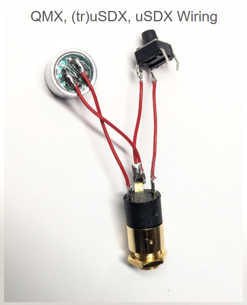
The K6ARK Mini Mic wiring for the QMX
In operation, the QMX ignores the microphone element when in CW mode. When in SSB mode the DIT side of the paddle is the PTT. Speak into the microphone as you normally would very close to the your lips. The one thing to watch out for is that you only press the DIT side. If you press the DAH side down as well you will bypass the mic so audio is feed to the radio resulting in no output power. The radio is no worse for wear should you do that. I have found that there is just enough room to rest you thumb on the edge of the PCB which allows for easy press of the DIT side to activate PTT.
Is this mod the most comfortable way to operate the QMX? For me, it is not, but its pretty darn cool and if you are a gram counter you might just like it. Adding the mic will not allow for the use Ara’s QMX adaptor for the tiny paddle. It will need to tweaking to allow for the microphone. I’m gonna drag my feet attempting that and hope someone else does that before I give it a try.
Purpose: Build a resonant 40-10-meter End Fed Halfwave Antenna that does not require a tuner and minimal operator interventions to switch bands. The antenna needs to have enough bandwidth to support both the voice and CW portions of each band. (Spoiler: I ended up getting 60 meters as well along the way.)
Background: After a couple hundred Summits On The Air (SOTA) activations I have come to realize that once I get my operating station setup I like to just stay situated while running all of the desired bands and chasing other summits. I am not a fan of having to get up and fiddle with antenna links and then get resituated. This is one of the reasons I really enjoy my radio and antenna kit combos that allow for this style of operating. My KX2 and KH1 are simply marvelous in that regard with their built-in tuners. My MTR3B v4 with its 40, 20 and 15 meter bands works great with a EFHW (built from a K6ARK kit) as it is resonant on all of that radio’s bands. I have also built a few trapped EFHW antennas. My MTR3B v2(LED) and SW-3B both use a 40-30-20 trapped EFHW for their bands. I have made trapped EFHW using four traps that supports 40-15 for use with my CFT-1 radio. These rigs are CW only rigs so bandwidth was not much of a concern.
Challenges: I have had good success with building trapped EFHWs. I have made antennas using three, four and even five traps. The more traps you add the more finnicky and iterative the trimming/tuning process becomes. In addition some of your bands are going to have greatly reduced bandwidth. This has not been an issue with my CW only rigs, but for the QMX and other non-tuner SSB and CW radios I needed an antenna with better bandwidth while not having to get up for every band change. Over the course of researching the traps and bandwidth issues I came across an interesting antenna that might solve my issue.
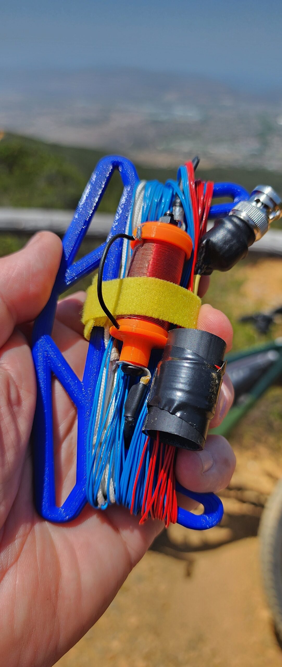
Inspiration: During the course of the previous trapped antenna projects research, I found an excellent article about building a portable 7-Band EFHW by Stephan M Schmid, HB9EAJ. I liked his approach of using a single loading coil for 60, 30 and 17 that can be bypassed making the antenna resonant on 40, 20, 15 and 10 meter bands I noticed in his measurements that the 10M band did not have good VSWR. Merging his antenna design with a classic 49:1 EFHW design with its loading coil for 20-15-10 could improve on that antenna. I would just need to add a link for 12M to cover all of the bands while minimizing the number of times I would need to go for a stroll to change bands.
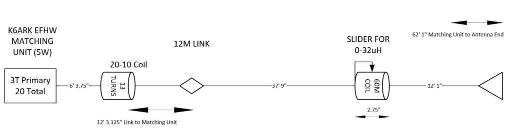
The starting antenna – The classic 49:1 with tuning coil
This classic end-fed half wave antenna would get merged with HB9EAJ’s antenna which used a loading coil that can be bypassed. When engaged the antenna is resonant on 60, 30 and 17 meters. When bypassed the antenna is resonant 40, 20, 15 and 10.
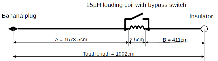
HB9EAJ 60-10M antenna (the 64:1 matching unit of his design is not depicted)
For the 25uH loading coil used with HB9EAJ’s design, I already had a coil that would work. I recently made the K6ARK mini KH1 loading coil. https://www.printables.com/model/1132060-elecraft-kh1-mini-screwdriver-loading-coil I really do not use it with that radio as I prefer to put up a wire for the lower bands. Repurposing this as my 60M loading coil with its adjustment ring will also function as a bypass switch. With all of the coils engaged I measured the inductance at 32uh. Using the slider it could be adjusted to right on 25uh.
The Antenna Build
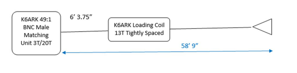
I built the EFHW matching unit using one of K6ARK’s kit with 3 turns on the primary and a total of 20 total. That works out to 44.4:1 vice the traditional 49:1 but it was recommended by Adam as efficient number of turns for the higher bands down to 40. I have had good results with his kits in the past and I have yet to find a more compact design than his configuration.
I build all of my matching units with a 2mm banana socket on the end so I can change wires as my antenna follies change. I installed the first wire segment (I used 26ga stranded wire, with PTFE jacket) with the loading coil form provided with Adam’s kit. I located the coil 6’ 3.375” from where the wire exits the matching transformer. I placed 13 turns tightly wound on the coil form. I kept it in place with electrical tap. I’m going to refer to this coil as the 20-10 coil from this point forward.
I spooled out an additional amount of wire and trimmed it for resonance on 12 meters (12’ 3.75″ from the matching unit). VSWR was 1.17. Note: If you later have to adjust the 20-10 coil, you may detune the link a little but the bottom of the VSWR curve is pretty wide for 12 meters so you should still have good VSWR.
I installed a link using 2mm banana plugs using a 2mm banana plug and socket. Here is Adam’s how to video.
From the installed link, Add additional wire for a total length of 51 feet as measured from a straight line from the matching unit including the coil. It is not necessary to trim for resonance on 17 meters (full wave length) at this point. Its worth noting that HB9EAJ’s design called for 55’. With the loading coil, you should not need a full 55’ but you may want to add a little more than 51’.
Install the 60M loading coil (K6ARK’s KH1 coil) to the end of the wire. You will be trimming or adding to this wire so do not be concerned about using a wire lug at this point. Just capture the wire on the coil using a nut and washer.
Next add on the final segment which should end up around 12’ 1” long. I would cut the wire long and fold it back on itself for now.
Ensure the coil is completely bypassed. This will be referred to here on as the 40 meter mode. I trimmed the end of the antenna wire for resonance in the 40M band. Now is a good time to read my future design consideration below.
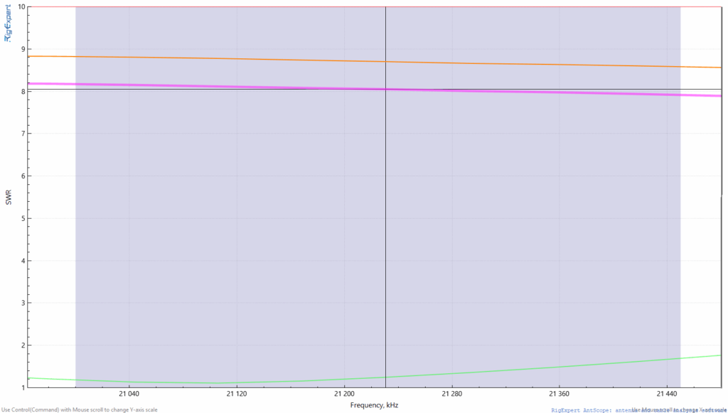
Check 20, 15 and 10 meters for their resonance. Adjust the 20-10M coil as necessary. My particularly build required me spreading the 13 turns slightly to get the 20-, 15- and 10-meter bands to where I wanted them. I was able to get 1.0 SWR on 20M at 14.080 with good VSWR across the entire band. 15M was good as well with resonance in the CW portion. 10M VSWR was good through the entire CW portion and up through the technician voice portion.
Ensure you are happy with the 40M mode before proceeding.
Now move the 60-meter coil to the nearly fully engaged point. Slide the coil tap/slider back and forth until you achieve resonance in the 60M band (5.36Mhz would be center of the band). Make a note of where this is at on the coil. For me this was with 2 turns showing between the slider and the end of form at the antenna end.
Now check the resonant points for 30 and 17 meters. If the resonant point is above the bands, you need to add more wire on radio side of the 60M coil and take away wire on the antenna end side of the 60M coil. (moving the coil towards the end of the antenna) If the resonant point is below the band you need to remove wire from the radio side of the coil and add wire to the antenna side of coil. (Move the coil towards the matching unit)
The net result of every iteration should be the overall length of the antenna should remain the same. After each iteration, bypass the 60M coil and verify that 40, 20, 15 and 10 meters are still good. Retrim/tweak the 40M mode before your next iteration of the 60M mode adjustments
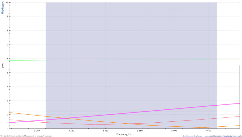
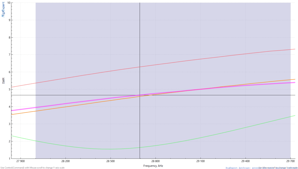
Keep repeating the process of tuning for 60M and checking for 30M and 17M until they come into acceptable range. If you look at my SWR graphs you see that I have three sets of plots (orange, purple and green). The orange is the coil fully engaged and the resonance being below the 60M band. The blue plot is for 60M resonance in the middle of the band with about two turns showing between the slider and the full engaged end of the coil. There is acceptable VSWR (under 2.0) on 30 and 17 meters. The green plot is for five turns showing between fully engaged and the slider with resonance at the upper end of the 60-meter band. Again, good VSWR on 30 and 17 meters. Note that all three measurements show the that resonance is a little below the band for 17 meters. With this design you could move the slider to move that resonance to be dead on 17 meters if you wanted to.
Final Build Measurements
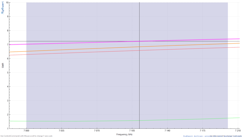
Green is VSWR in 40M Mode. Orange, Pink & Violet is 60M mode between 2-7 turns showing between slider and fully engaged. Blue is with the 12M link open.
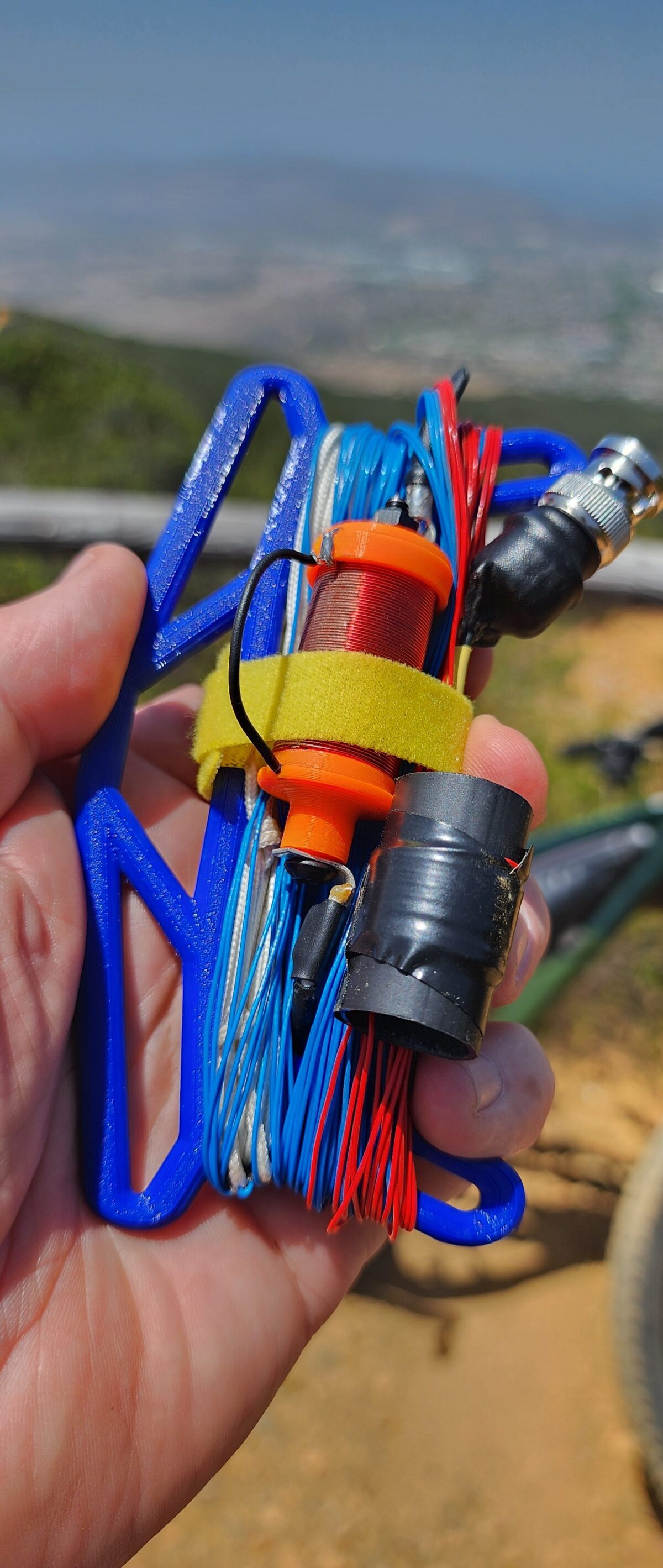
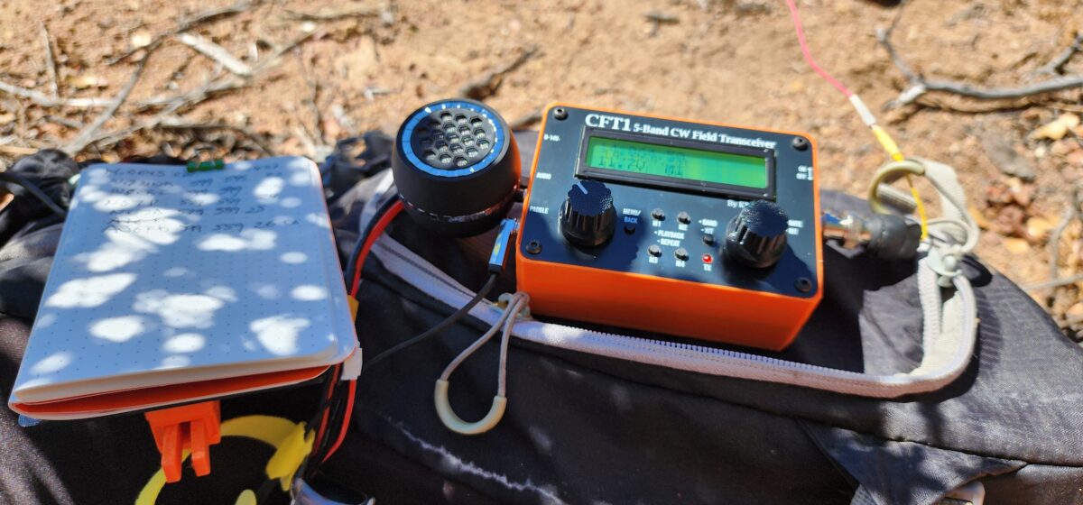
Stowed and ready to go!
Future design considerations: The HB9EAJ design uses a fixed 60M coil of a fixed value that is either in or out. The coil I used is fully adjustable and has probably seven or eight more turns than needed. When I built the antenna’s 40 meter “mode”, I had the 60M coil completely bypassed. You could build out the 40M mode of this antenna with just a couple of turns engaged in the coil. This would allow you to electrically shorten the antenna in 40M mode a little in the field if conditions warrant. This would most like allow you to push a bit further up the 10M band as well. The down side to this approach is that you have to think about those two turns when setting up vice just pushing the slider it all the way to the end. For the 60M mode if you did not want to think about how many turns need to be showing for 60, 30 and 17 you could short out turns on the end the coil with a bit of of solder so all you had to do was slide to one end of the other. I personally like the ability to make some adjustments. The next build of this antenna will leave a couple of turns engaged in the 40M mode and mark the spot it needs to be on the turns with a Sharpie.
Counterpoise: Much like HB9EAJ’s research I did not find using a counterpoise to really benefit this design much at all. The adjustability of the coil with my variation should allow for any tweaks that would be needed in the field.
60M VSWR Plot
40M VSWR Plot (Green)
30M VSWR Plot
20M VSWR Plot
17M VSWR Plot
15M VSWR Plot (Green)
12 VSWR Plot with link open (Blue)
10M VSWR Plot (Green)
Final thoughts: I am quite happy with my variation/marriage of a couple of good antenna designs. The 20-10 coil used in the classic EFHW design brought in the 10 meter VSWR down quite nicely. The use of the adjustable coil adds a bit of versatility for different setup conditions in the field. The link for 12 meters is a plus as well. I don’t think I did enough with this to call my design but I am okay with calling it the N6MTB 6010 EFHW build.
Purpose: Build and 40-10-meter End Fed Halfwave Antenna that was resonant on all seven bands in that range.
Background: After a couple hundred Summits On The Air (SOTA) activations I have come to realize once I get my operating station setup I like to just stay situated and run all of the desired bands and chasing other summits. I am not a fan of having to getup and fiddle with antenna links and then get resituated. This is one of the reasons I really enjoy my radio and antenna kit combos that allow for this style of operating. My KX2 and KH1 are simply marvelous in that regard with their built-in tuner. My MTR3B v4 with 40, 20 and 15 work great with a EFHW (built from a K6ARK kit) as it is resonant on all of that radios bands. I have also built a few trapped EFHW antennas. My MTR3B v2(LED) and AWS-3B both use a 40-30-20 trapped EFHW for their bands. I have made trapped EFHW using four traps that supports 40-15 for use with my CFT-1 radio. I have a QMX that I have modified for use on 40-10. I currently use and EFRW along with an Elecraft T-1 tuner. The tuner is about as tiny as they come in that range but it is larger than radio. Making a hybrid EFHW that is both resonant on 40-10 would make for a very compact tiddy radio kit.
Challenges: A quote I first heard from David Casler, KE0OG, comes to mind here “Everything Affects Everything” when building antennas and particularly when dealing with trapped antennas. My 40-30-20 trapped antenna required and little tweaking of the traps as the two traps used in that setup affected one another. The four traps used with my 40-15 build required no less than six full iterations of fine tuning all of the traps to get all of the bands in line. It ultimately ended up be good antenna but the process was a frustrating affair. Trying to build this antenna with three traps and a 20,15,10 loading coil is expected at least that frustrating.
Starting Antenna: I’m starting with this antenna design which works very well on 40,20,15 and 10. This antenna is a dedicated antenna that lives in my MTR3B v4 kit.
The Traps:
The Traps:
I reviewed quite a bit of literature and videos on the subject of building traps. I have previous used traps from QRPGuys. If you have components there is a nice shared PCB project on OSHPark that is what I am currently using. https://oshpark.com/shared_projects/WBU7X6sR The board will slide into a T50 or larger torroid without modification. I use my bench grinder to trim down one side to allow a T37 torroid to slide over if I am using that size.
I used https://toroids.info/T50-2.php as my primary calculation tool. Prior to making my L-C combination selections I went through a number of published trap designs I inputted their selections into the calculator. Of particularly concern for me was the ohm values. My thinking was that the higher ohm values may reduced the amount of interaction that occurs between the traps. The higher ohmic values are typically gain by using a lower capacitor value and a high inductance value for a given resonant frequency.
Trap values
12M Trap Values: Resonant at 24.885Mhz, T37-6 toroid with 23 turns (started with 25) with a 22pf cap. Estimated Ohms 291
17M Trap Values: Resonant at 18.0679Mz, T50-2 toroid with 37 turns (started with 40) with a 10pf cap.
30M Trap Values: Resonant at 10.099Mhz, T50-2 toroid with 40 turns (started with 43) with a 27pf cap.
Build Step Notes:
The K6ARK Matching Unit was built with 3T Primary, 20T secondary. The loading coil was placed the same distance as in my previous build. I took 1 turnout of the coil for a total of 12 turns compressed together. My thinking is that this is a starting point to compensate for the loading that will occur from the traps in the 15 through 40M range.
12 meter trap: Obtained a good VSWR measure of 1.16. Did not record the length at this point as I’m sure it is going to change. There was a lot of trimming required.
17 meter trap: Obtained a 1.6 VSWR with a lot of trimming.
30 meter trap: Best VSWR I could obtain was 2.1. Will revisit when it is fully built. I may need to try using a counter poise.
Added the 40M wire segment and trimmed. Was able to get the VSWR down to 1.3 at 7.045Mhz. Acceptable
I now went through and measured all of the bands.
40M 1.3 @ 7.045
30M 1.96 @ 10.13
20M – No resonance at all MAX VSWR
17M – 1.47 @19.975
15M – No resonance at all MAX VSWR
12M – 1.07 @25.025
10M – No resonance at all MAX VSWR
Conclusions:
I expected there to be some shift in resonance and VSWR with the trapped bands that would need some tweaking but I was quite surprised that there was no resonance with the harmonics of 40M. It like the traps acted like harmonic suppressors instead of presenting themselves as additional wire length. The thought of fully trapped EFHW for 40-10 using six traps seems like a nightmare.
I think the easiest approach would be to create at loaded EFHW like I have previously done with links for 12, 17 and 30.
Next round of tinkering
Thoughts A: The 30M trap has the most inductance. I wonder if it could be the main cause of the harmonic suppression of 20, 15 and 10 meters.
Action A: Instead of physically removing the trap, I solder a jumper wire on the trap board to electrically bypass the board. I then added a segment of wire onto the end of the 40M segment to tune the 40 segment with. I did not add enough wire but I was able to get the a good VSWR a bit above the 40M band. I checked to see if there was any sign of resonance at 20, 15 and 10.
Conclusion A: The 30M coil alone was not the cause of the harmonic suppression.
Thoughts B: I really would not like to build and six-trap EFHW antenna as I know the interactions between the traps would be exceeding tedious to tune. But I could see myself making a combination of trapped and linked EFHW. Links in the section of the antenna that are easy to get to such as 10, 12 and 15 and 30. Use traps for the bands that are higher up in an inverted V such as 20 and 17. On brushy summits the far end of the V can be a pain to get to so maybe a 30M trap should be in the mix. Traps for 30, 20 and 17 and links for 15, 12, 10.
After a break I came back for some more tinkering
Thoughts C: The antenna is already built, why not continue to see what the remaining traps do to the harmonic suppression.
Action C: Bypass the 17M trap add wire to the end of the antenna to compensate for the reduction in loading. Roughly tune the wire into the 40M band
Results of C:
40M: 1.21 @ 7.13
30M: MAX VSWR
20M: 2.1 @ 13.85
17M: MAX VSWR
15M: 3.6 @ 20.625
12M 1.2 @ 25.00
10M 4.7 @ 29.00
Conclusion C: The bypass/removal of the 17M and the 30M trap restored the 20, 15 and 10 harmonics to some degree. I believe the 20M harmonic could be tuned into the band with a usable VSWR. While there is a reduction of VSWR near the 15M and 10M bands indicating that harmonics are present, I doubt they could be tuned into a usable state. With a trap being inductive below its resonant frequency and capacitive above it resonant frequency the resonant frequencies shown reflect that. With the overall wire trimmed for 7.13, the harmonic for 20M should at the upper end of the band, but the 12M trap and loading coil are pushing it below the band at 13.85. The same applies for the 15M band. The 10M band is actually near high end of the band which could be indicative of the capacitive nature of the 12M trap above its frequency
Thought D: Do I dare attempt at six-trap EFHW? That seems to be a recipe in frustration. While I have done a four trap EFHW before it was a bit of a pain. Maybe build a two-link, four-trap EFHW for 10-40M. Use links for 10 and 12M. Use traps for 15, 17, 20 and 30 with the final segment being tuned for 40M.
Overall Thoughts: I have to classify this project from the perspective of building a working antenna that used both the harmonic properties of the classic 40M EFHW antenna and the usefulness of the traps as a failure. From the perspective of learning something in the process it was definitely a success that is going to inform furthering tinkering.
Another modification I did to my QMX was to change the band support to make it work on 40-10 meters. I had previously modified this radio for 60-15 meters (this was before QRP-Labs offered a kit for those bands). Dan, AI6XG, came up with a better mod for use on 40-10 and latter further modified my rig for 40-10 using Dan’s notes.
Here is a quick short showing off both the band mod and the touch keying mod.
Since then I have updated to the firmware that supports SSB and all is well with that and my mods. I’m currently using and End Fed Random Wire with a T-1 tuner to cover all those bands. My next project with this rig is to make a trapped/linked end fed half wave antenna to eliminate the use of the tuner.