Purpose: Build a resonant 40-10-meter End Fed Halfwave Antenna that does not require a tuner and minimal operator interventions to switch bands. The antenna needs to have enough bandwidth to support both the voice and CW portions of each band. (Spoiler: I ended up getting 60 meters as well along the way.)
Background: After a couple hundred Summits On The Air (SOTA) activations I have come to realize that once I get my operating station setup I like to just stay situated while running all of the desired bands and chasing other summits. I am not a fan of having to get up and fiddle with antenna links and then get resituated. This is one of the reasons I really enjoy my radio and antenna kit combos that allow for this style of operating. My KX2 and KH1 are simply marvelous in that regard with their built-in tuners. My MTR3B v4 with its 40, 20 and 15 meter bands works great with a EFHW (built from a K6ARK kit) as it is resonant on all of that radio’s bands. I have also built a few trapped EFHW antennas. My MTR3B v2(LED) and SW-3B both use a 40-30-20 trapped EFHW for their bands. I have made trapped EFHW using four traps that supports 40-15 for use with my CFT-1 radio. These rigs are CW only rigs so bandwidth was not much of a concern.
Challenges: I have had good success with building trapped EFHWs. I have made antennas using three, four and even five traps. The more traps you add the more finnicky and iterative the trimming/tuning process becomes. In addition some of your bands are going to have greatly reduced bandwidth. This has not been an issue with my CW only rigs, but for the QMX and other non-tuner SSB and CW radios I needed an antenna with better bandwidth while not having to get up for every band change. Over the course of researching the traps and bandwidth issues I came across an interesting antenna that might solve my issue.
Inspiration: During the course of the previous trapped antenna projects research, I found an excellent article about building a portable 7-Band EFHW by Stephan M Schmid, HB9EAJ. I liked his approach of using a single loading coil for 60, 30 and 17 that can be bypassed making the antenna resonant on 40, 20, 15 and 10 meter bands I noticed in his measurements that the 10M band did not have good VSWR. Merging his antenna design with a classic 49:1 EFHW design with its loading coil for 20-15-10 could improve on that antenna. I would just need to add a link for 12M to cover all of the bands while minimizing the number of times I would need to go for a stroll to change bands.

The starting antenna – The classic 49:1 with tuning coil
This classic end-fed half wave antenna would get merged with HB9EAJ’s antenna which used a loading coil that can be bypassed. When engaged the antenna is resonant on 60, 30 and 17 meters. When bypassed the antenna is resonant 40, 20, 15 and 10.
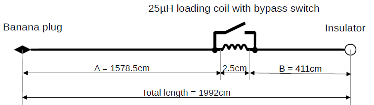
HB9EAJ 60-10M antenna (the 64:1 matching unit of his design is not depicted)
For the 25uH loading coil used with HB9EAJ’s design, I already had a coil that would work. I recently made the K6ARK mini KH1 loading coil. https://www.printables.com/model/1132060-elecraft-kh1-mini-screwdriver-loading-coil I really do not use it with that radio as I prefer to put up a wire for the lower bands. Repurposing this as my 60M loading coil with its adjustment ring will also function as a bypass switch. With all of the coils engaged I measured the inductance at 32uh. Using the slider it could be adjusted to right on 25uh.
The Antenna Build
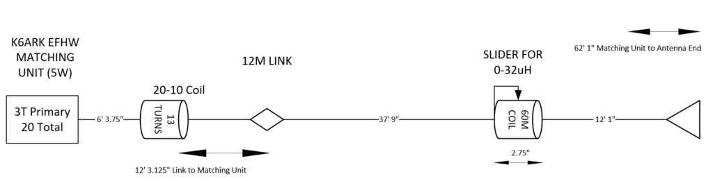
- I built the EFHW matching unit using one of K6ARK’s kit with 3 turns on the primary and a total of 20 total. That works out to 44.4:1 vice the traditional 49:1 but it was recommended by Adam as efficient number of turns for the higher bands down to 40. I have had good results with his kits in the past and I have yet to find a more compact design than his configuration.
- I build all of my matching units with a 2mm banana socket on the end so I can change wires as my antenna follies change. I installed the first wire segment (I used 26ga stranded wire, with PTFE jacket) with the loading coil form provided with Adam’s kit. I located the coil 6’ 3.375” from where the wire exits the matching transformer. I placed 13 turns tightly wound on the coil form. I kept it in place with electrical tap. I’m going to refer to this coil as the 20-10 coil from this point forward.
- I spooled out an additional amount of wire and trimmed it for resonance on 12 meters (12’ 3.75″ from the matching unit). VSWR was 1.17. Note: If you later have to adjust the 20-10 coil, you may detune the link a little but the bottom of the VSWR curve is pretty wide for 12 meters so you should still have good VSWR.
- I installed a link using 2mm banana plugs using a 2mm banana plug and socket. Here is Adam’s how to video.
- From the installed link, Add additional wire for a total length of 51 feet as measured from a straight line from the matching unit including the coil. It is not necessary to trim for resonance on 17 meters (full wave length) at this point. Its worth noting that HB9EAJ’s design called for 55’. With the loading coil, you should not need a full 55’ but you may want to add a little more than 51’.
- Install the 60M loading coil (K6ARK’s KH1 coil) to the end of the wire. You will be trimming or adding to this wire so do not be concerned about using a wire lug at this point. Just capture the wire on the coil using a nut and washer.
- Next add on the final segment which should end up around 12’ 1” long. I would cut the wire long and fold it back on itself for now.
- Ensure the coil is completely bypassed. This will be referred to here on as the 40 meter mode. I trimmed the end of the antenna wire for resonance in the 40M band. Now is a good time to read my future design consideration below.
- Check 20, 15 and 10 meters for their resonance. Adjust the 20-10M coil as necessary. My particularly build required me spreading the 13 turns slightly to get the 20-, 15- and 10-meter bands to where I wanted them. I was able to get 1.0 SWR on 20M at 14.080 with good VSWR across the entire band. 15M was good as well with resonance in the CW portion. 10M VSWR was good through the entire CW portion and up through the technician voice portion.
- Ensure you are happy with the 40M mode before proceeding.
- Now move the 60-meter coil to the nearly fully engaged point. Slide the coil tap/slider back and forth until you achieve resonance in the 60M band (5.36Mhz would be center of the band). Make a note of where this is at on the coil. For me this was with 2 turns showing between the slider and the end of form at the antenna end.
- Now check the resonant points for 30 and 17 meters. If the resonant point is above the bands, you need to add more wire on radio side of the 60M coil and take away wire on the antenna end side of the 60M coil. (moving the coil towards the end of the antenna) If the resonant point is below the band you need to remove wire from the radio side of the coil and add wire to the antenna side of coil. (Move the coil towards the matching unit)
- The net result of every iteration should be the overall length of the antenna should remain the same. After each iteration, bypass the 60M coil and verify that 40, 20, 15 and 10 meters are still good. Retrim/tweak the 40M mode before your next iteration of the 60M mode adjustments
- Keep repeating the process of tuning for 60M and checking for 30M and 17M until they come into acceptable range. If you look at my SWR graphs you see that I have three sets of plots (orange, purple and green). The orange is the coil fully engaged and the resonance being below the 60M band. The blue plot is for 60M resonance in the middle of the band with about two turns showing between the slider and the full engaged end of the coil. There is acceptable VSWR (under 2.0) on 30 and 17 meters. The green plot is for five turns showing between fully engaged and the slider with resonance at the upper end of the 60-meter band. Again, good VSWR on 30 and 17 meters. Note that all three measurements show the that resonance is a little below the band for 17 meters. With this design you could move the slider to move that resonance to be dead on 17 meters if you wanted to.
Final Build Measurements

Green is VSWR in 40M Mode. Orange, Pink & Violet is 60M mode between 2-7 turns showing between slider and fully engaged. Blue is with the 12M link open.
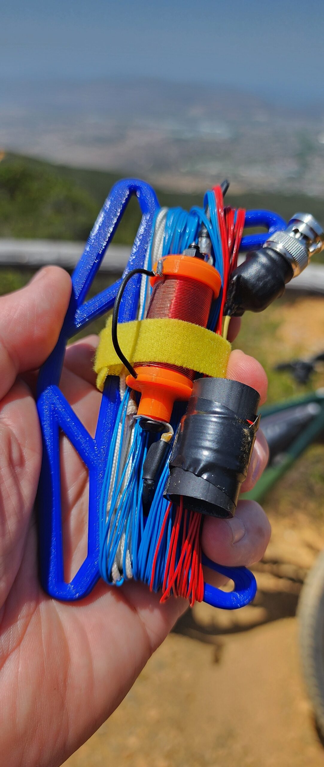
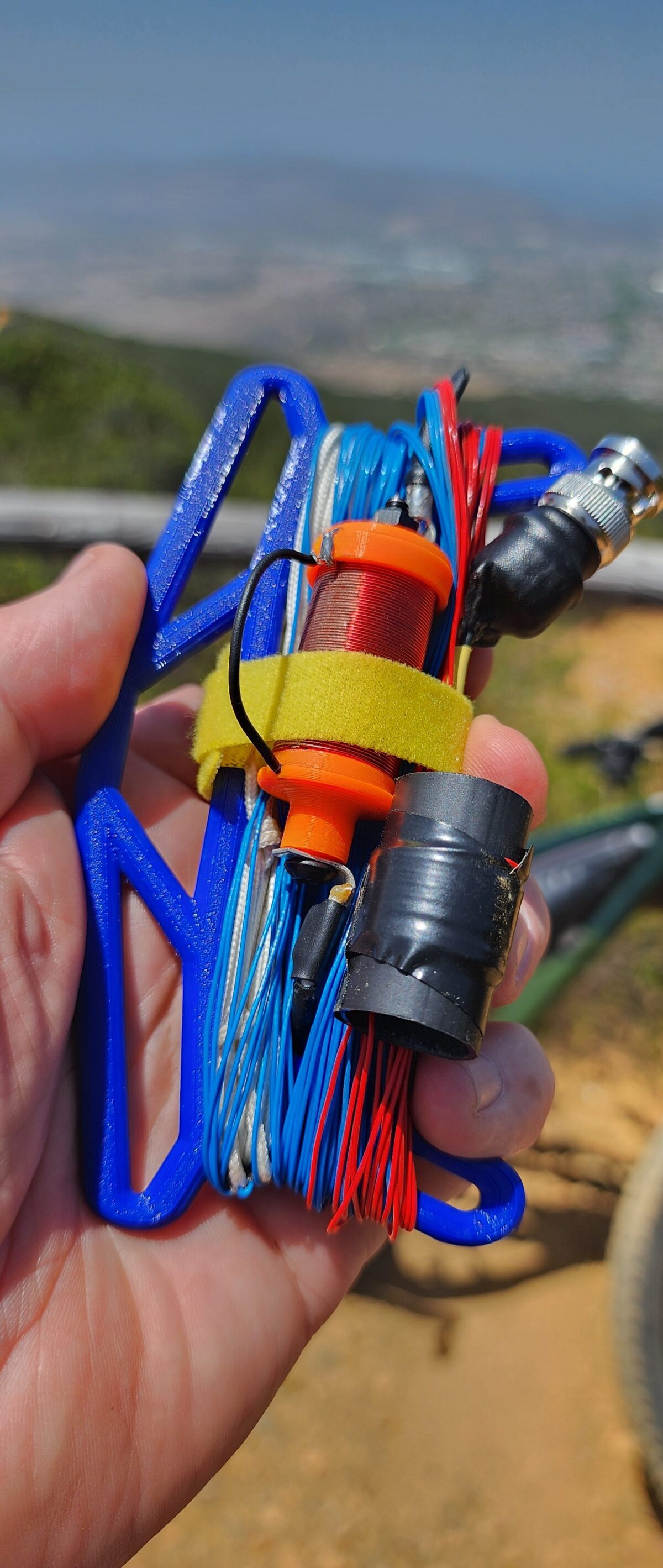
Stowed and ready to go!
Future design considerations: The HB9EAJ design uses a fixed 60M coil of a fixed value that is either in or out. The coil I used is fully adjustable and has probably seven or eight more turns than needed. When I built the antenna’s 40 meter “mode”, I had the 60M coil completely bypassed. You could build out the 40M mode of this antenna with just a couple of turns engaged in the coil. This would allow you to electrically shorten the antenna in 40M mode a little in the field if conditions warrant. This would most like allow you to push a bit further up the 10M band as well. The down side to this approach is that you have to think about those two turns when setting up vice just pushing the slider it all the way to the end. For the 60M mode if you did not want to think about how many turns need to be showing for 60, 30 and 17 you could short out turns on the end the coil with a bit of of solder so all you had to do was slide to one end of the other. I personally like the ability to make some adjustments. The next build of this antenna will leave a couple of turns engaged in the 40M mode and mark the spot it needs to be on the turns with a Sharpie.
Counterpoise: Much like HB9EAJ’s research I did not find using a counterpoise to really benefit this design much at all. The adjustability of the coil with my variation should allow for any tweaks that would be needed in the field.
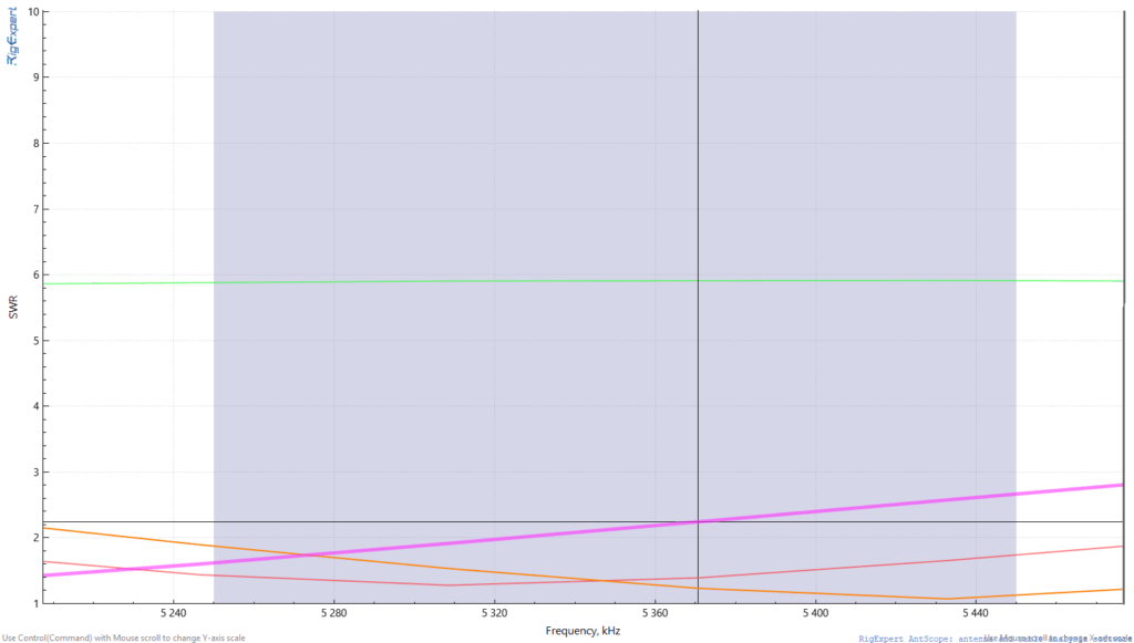
60M VSWR Plot
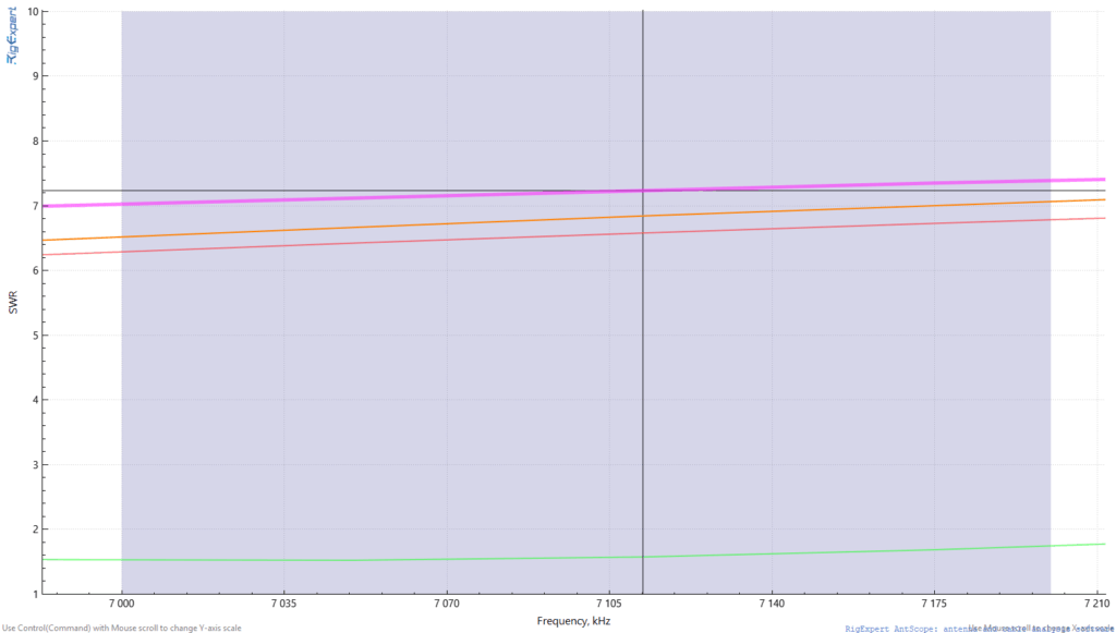
40M VSWR Plot (Green)

30M VSWR Plot

20M VSWR Plot

17M VSWR Plot
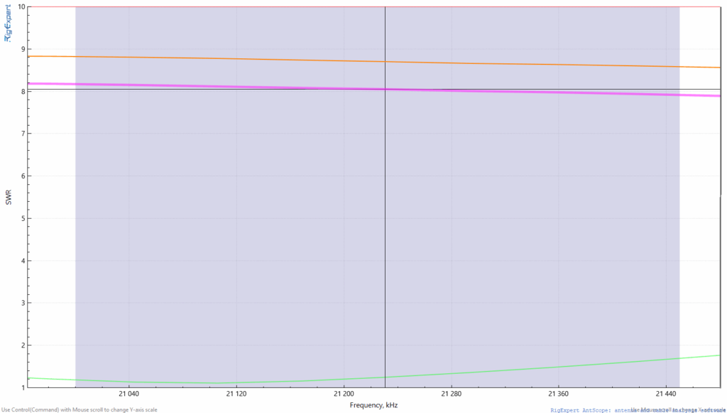
15M VSWR Plot (Green)

12 VSWR Plot with link open (Blue)
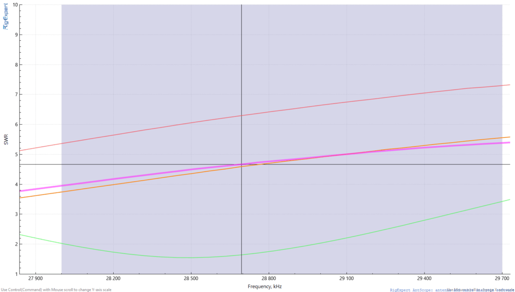
10M VSWR Plot (Green)
Final thoughts: I am quite happy with my variation/marriage of a couple of good antenna designs. The 20-10 coil used in the classic EFHW design brought in the 10 meter VSWR down quite nicely. The use of the adjustable coil adds a bit of versatility for different setup conditions in the field. The link for 12 meters is a plus as well. I don’t think I did enough with this to call my design but I am okay with calling it the N6MTB 6010 EFHW build.