Purpose: Build and 40-10-meter End Fed Halfwave Antenna that was resonant on all seven bands in that range.
Background: After a couple hundred Summits On The Air (SOTA) activations I have come to realize once I get my operating station setup I like to just stay situated and run all of the desired bands and chasing other summits. I am not a fan of having to getup and fiddle with antenna links and then get resituated. This is one of the reasons I really enjoy my radio and antenna kit combos that allow for this style of operating. My KX2 and KH1 are simply marvelous in that regard with their built-in tuner. My MTR3B v4 with 40, 20 and 15 work great with a EFHW (built from a K6ARK kit) as it is resonant on all of that radios bands. I have also built a few trapped EFHW antennas. My MTR3B v2(LED) and AWS-3B both use a 40-30-20 trapped EFHW for their bands. I have made trapped EFHW using four traps that supports 40-15 for use with my CFT-1 radio. I have a QMX that I have modified for use on 40-10. I currently use and EFRW along with an Elecraft T-1 tuner. The tuner is about as tiny as they come in that range but it is larger than radio. Making a hybrid EFHW that is both resonant on 40-10 would make for a very compact tiddy radio kit.
Challenges: A quote I first heard from David Casler, KE0OG, comes to mind here “Everything Affects Everything” when building antennas and particularly when dealing with trapped antennas. My 40-30-20 trapped antenna required and little tweaking of the traps as the two traps used in that setup affected one another. The four traps used with my 40-15 build required no less than six full iterations of fine tuning all of the traps to get all of the bands in line. It ultimately ended up be good antenna but the process was a frustrating affair. Trying to build this antenna with three traps and a 20,15,10 loading coil is expected at least that frustrating.
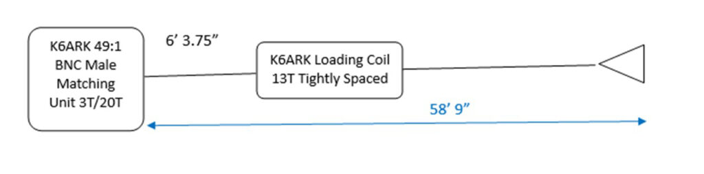
Starting Antenna: I’m starting with this antenna design which works very well on 40,20,15 and 10. This antenna is a dedicated antenna that lives in my MTR3B v4 kit.
The Traps:
The Traps:
- I reviewed quite a bit of literature and videos on the subject of building traps. I have previous used traps from QRPGuys. If you have components there is a nice shared PCB project on OSHPark that is what I am currently using. https://oshpark.com/shared_projects/WBU7X6sR The board will slide into a T50 or larger torroid without modification. I use my bench grinder to trim down one side to allow a T37 torroid to slide over if I am using that size.
- I used https://toroids.info/T50-2.php as my primary calculation tool. Prior to making my L-C combination selections I went through a number of published trap designs I inputted their selections into the calculator. Of particularly concern for me was the ohm values. My thinking was that the higher ohm values may reduced the amount of interaction that occurs between the traps. The higher ohmic values are typically gain by using a lower capacitor value and a high inductance value for a given resonant frequency.
- Trap values
- 12M Trap Values: Resonant at 24.885Mhz, T37-6 toroid with 23 turns (started with 25) with a 22pf cap. Estimated Ohms 291
- 17M Trap Values: Resonant at 18.0679Mz, T50-2 toroid with 37 turns (started with 40) with a 10pf cap.
- 30M Trap Values: Resonant at 10.099Mhz, T50-2 toroid with 40 turns (started with 43) with a 27pf cap.
Build Step Notes:
- The K6ARK Matching Unit was built with 3T Primary, 20T secondary. The loading coil was placed the same distance as in my previous build. I took 1 turnout of the coil for a total of 12 turns compressed together. My thinking is that this is a starting point to compensate for the loading that will occur from the traps in the 15 through 40M range.
- 12 meter trap: Obtained a good VSWR measure of 1.16. Did not record the length at this point as I’m sure it is going to change. There was a lot of trimming required.
- 17 meter trap: Obtained a 1.6 VSWR with a lot of trimming.
- 30 meter trap: Best VSWR I could obtain was 2.1. Will revisit when it is fully built. I may need to try using a counter poise.
- Added the 40M wire segment and trimmed. Was able to get the VSWR down to 1.3 at 7.045Mhz. Acceptable
I now went through and measured all of the bands.
- 40M 1.3 @ 7.045
- 30M 1.96 @ 10.13
- 20M – No resonance at all MAX VSWR
- 17M – 1.47 @19.975
- 15M – No resonance at all MAX VSWR
- 12M – 1.07 @25.025
- 10M – No resonance at all MAX VSWR
Conclusions:
I expected there to be some shift in resonance and VSWR with the trapped bands that would need some tweaking but I was quite surprised that there was no resonance with the harmonics of 40M. It like the traps acted like harmonic suppressors instead of presenting themselves as additional wire length. The thought of fully trapped EFHW for 40-10 using six traps seems like a nightmare.
I think the easiest approach would be to create at loaded EFHW like I have previously done with links for 12, 17 and 30.
Next round of tinkering
Thoughts A: The 30M trap has the most inductance. I wonder if it could be the main cause of the harmonic suppression of 20, 15 and 10 meters.
Action A: Instead of physically removing the trap, I solder a jumper wire on the trap board to electrically bypass the board. I then added a segment of wire onto the end of the 40M segment to tune the 40 segment with. I did not add enough wire but I was able to get the a good VSWR a bit above the 40M band. I checked to see if there was any sign of resonance at 20, 15 and 10.
Conclusion A: The 30M coil alone was not the cause of the harmonic suppression.
Thoughts B: I really would not like to build and six-trap EFHW antenna as I know the interactions between the traps would be exceeding tedious to tune. But I could see myself making a combination of trapped and linked EFHW. Links in the section of the antenna that are easy to get to such as 10, 12 and 15 and 30. Use traps for the bands that are higher up in an inverted V such as 20 and 17. On brushy summits the far end of the V can be a pain to get to so maybe a 30M trap should be in the mix. Traps for 30, 20 and 17 and links for 15, 12, 10.
After a break I came back for some more tinkering
Thoughts C: The antenna is already built, why not continue to see what the remaining traps do to the harmonic suppression.
Action C: Bypass the 17M trap add wire to the end of the antenna to compensate for the reduction in loading. Roughly tune the wire into the 40M band
Results of C:
40M: 1.21 @ 7.13
30M: MAX VSWR
20M: 2.1 @ 13.85
17M: MAX VSWR
15M: 3.6 @ 20.625
12M 1.2 @ 25.00
10M 4.7 @ 29.00
Conclusion C: The bypass/removal of the 17M and the 30M trap restored the 20, 15 and 10 harmonics to some degree. I believe the 20M harmonic could be tuned into the band with a usable VSWR. While there is a reduction of VSWR near the 15M and 10M bands indicating that harmonics are present, I doubt they could be tuned into a usable state. With a trap being inductive below its resonant frequency and capacitive above it resonant frequency the resonant frequencies shown reflect that. With the overall wire trimmed for 7.13, the harmonic for 20M should at the upper end of the band, but the 12M trap and loading coil are pushing it below the band at 13.85. The same applies for the 15M band. The 10M band is actually near high end of the band which could be indicative of the capacitive nature of the 12M trap above its frequency
Thought D: Do I dare attempt at six-trap EFHW? That seems to be a recipe in frustration. While I have done a four trap EFHW before it was a bit of a pain. Maybe build a two-link, four-trap EFHW for 10-40M. Use links for 10 and 12M. Use traps for 15, 17, 20 and 30 with the final segment being tuned for 40M.
Overall Thoughts: I have to classify this project from the perspective of building a working antenna that used both the harmonic properties of the classic 40M EFHW antenna and the usefulness of the traps as a failure. From the perspective of learning something in the process it was definitely a success that is going to inform furthering tinkering.
73,
Bill, N6MTB